
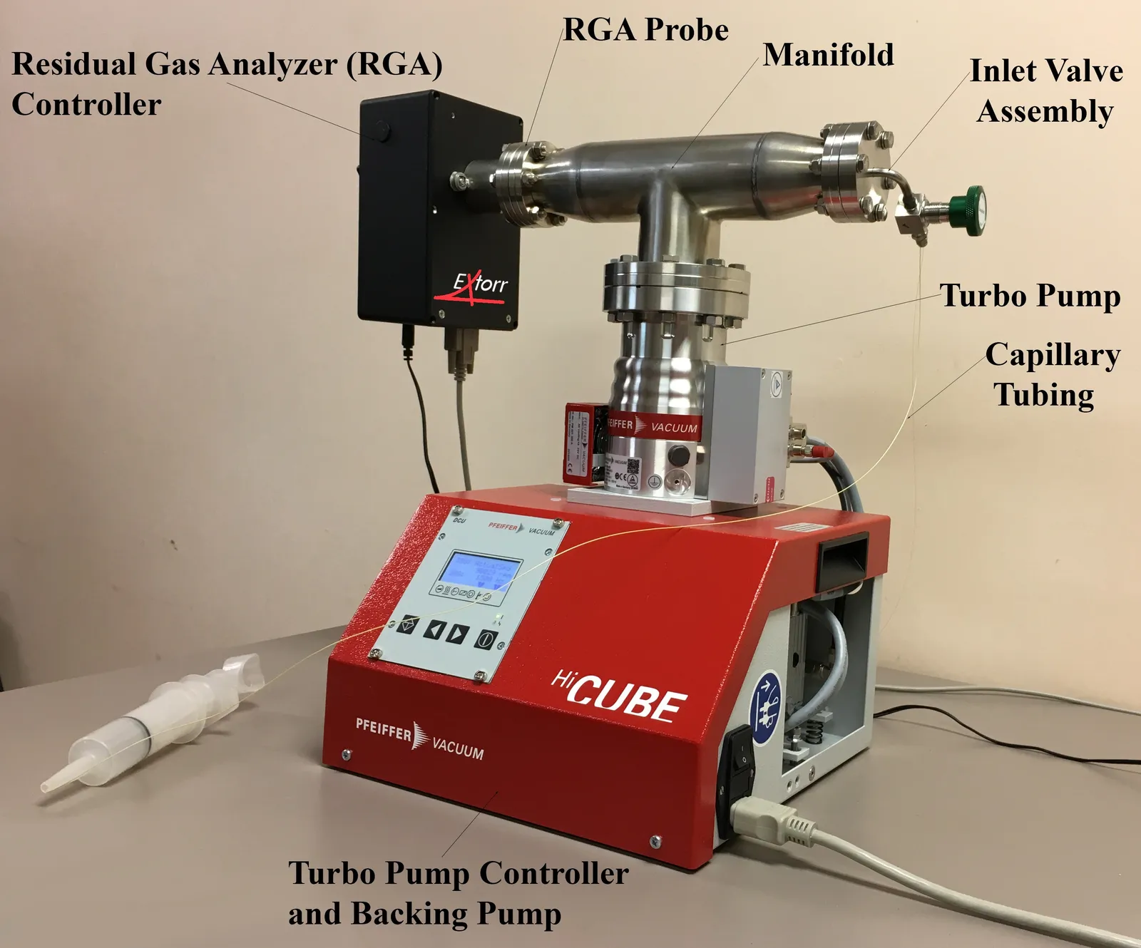
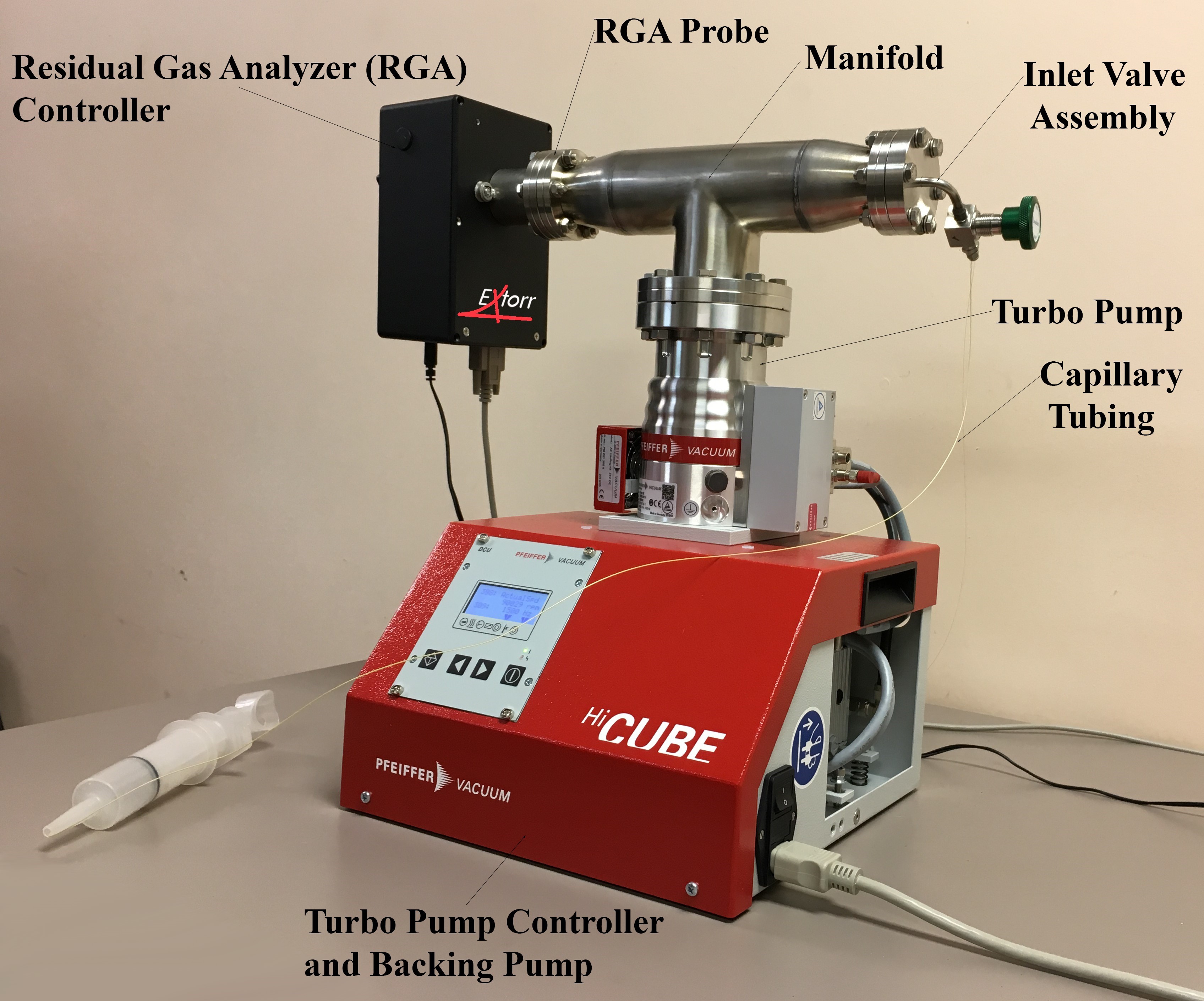
A residual gas analyzer is a mass spectrometer without a vacuum system, an inlet or a data system. It is normally mounted on an existing chamber to monitor vacuum quality. Put the analyzer in a manifold, add a pump to supply the high vacuum and a means of introducing a sample, and it becomes a basic mass spectrometer in its own right — one that may be suitable for your application.
The analyte and choosing an operating pressure
What you are measuring determines the pressure you can measure it at. Sensitivity, linearity and the rate at which the analyzer wears out are all set by the same decision — what total pressure the probe runs at while sampling — and they cannot be optimised separately. A higher operating pressure puts more of your analyte in front of the ionizer and lowers the concentration you can detect, and it also shortens the life of the filament, the ionizer and the mass filter, faster if the analyte is reactive. So the analyte sets the constraints, the operating pressure is the number you choose against them, and everything downstream — the capillary bore, the pump size, the manifold — follows from that.
None of this is particular to our instruments. Any quadrupole mass spectrometer behaves this way, and the same reasoning applies whoever built the analyzer you are designing around.
The linear range
A quadrupole's response is proportional to partial pressure over a limited range. Toward the top of that range the proportionality fails, for reasons that stack: the mean free path becomes short enough that ions collide with neutrals before reaching the detector, space charge in the ionizer begins to defocus the beam, and at high signal the detector itself saturates. Readings compress, so a peak twice as large no longer means twice as much gas.
In practice response stays linear up to roughly 10-5 Torr and degrades as you approach 10-4. Below the range, you are limited by the noise floor rather than by physics. Somewhere around 10-6 Torr is a reasonable place to start: comfortably inside the linear range, with a decade of headroom on either side.
What operating pressure costs you in sensitivity
Every species in the sample scales with the total pressure. Drop the operating pressure by a decade and every partial pressure drops by a decade with it, while the instrument's noise floor stays where it is. A tenfold reduction in operating pressure is a tenfold worse detection limit expressed as a concentration.
Put numbers on it. A 100 ppm species is 10-4 of the sample. At an operating pressure of 10-6 Torr it arrives at the ionizer as a partial pressure of 10-10 Torr. At 10-7 Torr it is 10-11 Torr. Both are measurable — an Extorr Faraday cup resolves about 2.4 × 10⁻¹² Torr at a 200 ms dwell, and an electron multiplier reaches the 10-14 range — but the margin above the noise, and therefore the precision of the number, is very different.
The background is part of your detection limit
A vacuum system is never empty. Even a clean, well-pumped stainless manifold shows a characteristic residual spectrum: hydrogen at 2, water at 18 with its fragments at 17 and 16, carbon monoxide and nitrogen sharing 28, oxygen at 32, argon at 40, carbon dioxide at 44, and hydrocarbon groups around 39 to 57 wherever there is oil. In an unbaked system water usually dominates, desorbing from the walls; after a bakeout hydrogen does, diffusing out of the steel itself.
For any given mass, the real detection limit is whichever is larger: the instrument's noise floor, or the background already sitting at that mass. An analyte at 28 competes with the CO and N2 that were there before the inlet was opened, and no amount of instrument sensitivity recovers it.
This interacts with operating pressure in a way that is easy to miss. Lowering the operating pressure reduces every partial pressure in the sample, but it does not reduce the background — that comes from the walls outgassing against the pumping speed, and does not care how much sample you admit. Drop the operating pressure by a decade and the analyte-to-background ratio drops by a decade with it. Past some point the analyte disappears into the residual spectrum rather than into the noise, and that point, not the instrument's noise floor, is the real limit on how far you can back off.
Two things follow. Record the background with the inlet valve shut before trusting any measurement — that spectrum is the true baseline, and it tells you which masses are usable. And where the analyte gives you a choice of fragments, pick one that lands where the background is quiet. Mass 28 is the classic trap: nitrogen and carbon monoxide are indistinguishable at unit resolution, and telling them apart means working from the minor peaks — N2 gives N+ at 14, CO gives C+ at 12 and O+ at 16, and an air leak brings O2 at 32 and argon at 40 with it.
Baking is the other lever, and it is worth doing properly when the background is what limits you. Heating the manifold and probe while pumping drives adsorbed water off the walls far faster than pumping alone: the water peak climbs sharply as it comes off, holds, then falls away, and the system settles a decade or two below where it started. Extorr probes take 300 °C with the CCU removed; the rest of the manifold is usually limited by whatever elastomer is in it, which is one of the arguments for an all-metal build. Expect to repeat it after any vent to atmosphere, and watch mass 18 to know when it is finished rather than working to a fixed time.
Reactivity and wear
Wear is a dose, not a concentration: it depends on how much of the reactive species passes the hot filament, the ionizer and the mass filter behind them, over how long. The same gas at a tenth the pressure does roughly a tenth the damage per hour, which is the lever operating pressure gives you. A filament is a consumable and an ionizer is replaceable; damage that reaches the quadrupole rods is neither, and it shows up as sensitivity and resolution quietly falling away rather than as anything failing outright.
Some of the more common examples follow. This is not an exhaustive list.
Halogens and halogenated compounds. Fluorine and chlorine bearing species — HF, F2, NF3, Cl2, HCl, and the fragments of fluorocarbons — attack the filament and the metal surfaces of the ionizer directly, and given enough exposure the quadrupole rods with them. These are the fastest way to consume a probe — the whole probe, not only its consumables — and the strongest argument for running at reduced pressure.
Sulfur compounds. H2S and its relatives corrode filaments and contacts, and tend to leave deposits that change the ionizer's behaviour before they destroy anything outright.
Oxygen and water. Benign by comparison, but not inert against a filament at temperature. Oxygen accelerates loss from a hot emitting surface, and continuous operation in a high oxygen background shortens filament life measurably. Thoria coated iridium tolerates this far better than bare tungsten, which is why it is the usual choice for anything but clean UHV.
Silicones. A different failure mode: vacuum greases, RTV sealants, mould release agents and outgassing from silicone tubing crack on the hot filament and leave insulating silica on the ionizer and on the quadrupole rods. Nothing corrodes, but an insulating film on a rod holds charge and distorts the field that does the mass separation, so sensitivity falls, peaks broaden and tuning drifts — and none of it pumps away. Keep silicones out of the system entirely rather than managing them with pressure.
Pump oil and hydrocarbons. Backstreamed oil carbonises on hot surfaces and leaves conductive or insulating films depending on where it lands, and it puts a hydrocarbon background across the spectrum that is hard to distinguish from hydrocarbons in the sample.
A worked example
Suppose the sample is air carrying 100 ppm of HF, and the measurement needs to run continuously.
HF appears at 20, with F+ at 19. Neither mass is clean by default: 19 carries H3O+ from water, and 20 carries doubly ionised argon out of the air you are sampling. So the background scan comes first, and a bakeout to knock down the water is worth doing before deciding anything about pressure.
At 10-6 Torr the HF arrives as 10-10 Torr, comfortably measurable, and the analyzer would give good numbers — for a while. Fluorine is about as hard on a probe as anything you are likely to sample, and it does not stop at the filament, so at that pressure and running continuously the whole probe becomes a consumable measured in weeks rather than years.
Choosing 10-7 Torr instead changes the arithmetic. The HF partial pressure becomes 10-11 Torr, while the dose reaching the filament falls by a factor of ten and the service interval extends by roughly the same. That brings the measurement closer to the Faraday cup's noise floor, and how close depends on the dwell time you are willing to give it. An electron multiplier lowers the noise floor substantially, buying back signal to noise and letting you scan faster for better confidence — strongly recommended in this situation. The detection limit is worse in absolute terms than it would have been at 10-6, but what you gave up was margin the application did not need, and what you bought was an instrument that survives the campaign.
That is the trade in general form. Work out the lowest concentration you genuinely have to resolve, establish the operating pressure that puts it a comfortable distance above the noise floor, and then run at the lowest pressure that still satisfies it. If the analyte is aggressive, consider whether the measurement really has to be continuous — sampling intermittently, with the inlet valve shut between measurements, cuts the dose in direct proportion to the duty cycle and often costs nothing that matters.
The manifold
The manifold is the tee that holds the probe, the pump and the inlet. Its size is not a packaging detail — it sets how fast the system pumps down and how quickly the analyzer responds to a change at the inlet.
Volume and conductance both matter, for different reasons. Volume sets how much gas has to be removed to reach working pressure, so a large manifold takes longer to pump down and longer to clear after a bakeout or a vent. Conductance matters because pressure is not uniform through a vacuum system: a long or narrow path between the probe and the pump restricts flow, so the probe sits at a higher pressure than the pump inlet, the background is higher than the pump's rating would suggest, and gas released from the walls lingers rather than being swept away.
Keep the probe close to the pump, keep the bore wide, and keep the internal surface area no larger than you need. Probe manifolds are made for this and come with a pump flange in ConFlat, ISO or KF. Nipples and adapters change the insertion depth or the flange type when a chamber port does not match.
The pump
Below about 10-3 Torr you need a turbomolecular pump with a backing pump behind it. A rough pump alone will not get you into the range where the quadrupole operates.
Two decisions matter more than headline pumping speed. First, whether the backing pump is dry: an oil-sealed rotary vane pump can backstream hydrocarbons into the system, and hydrocarbon peaks in every spectrum you take are difficult to distinguish from hydrocarbons in the thing you are measuring. A diaphragm-backed station avoids the argument entirely. Second, whether the pump has enough capacity for the gas load your inlet lets in — a sampling system deliberately admits gas continuously, so the pump has to remove it continuously while holding the probe in range.
There is a third if hydrogen is one of the things you care about, and it is the one people miss. A turbo pump's compression ratio for hydrogen is orders of magnitude lower than for nitrogen — thousands rather than billions — because the molecule is light enough to work its way back through the rotor. The consequence is that the hydrogen partial pressure at the turbo inlet is set largely by how much hydrogen is sitting in the foreline, which makes it the backing pump's problem rather than the turbo's. A backing pump that removes hydrogen poorly leaves it there, and it returns through the turbo as a background peak at mass 2 that no amount of pumping time clears.
This is the one place the oil argument goes the other way. A rotary vane pump reaches a far lower ultimate pressure and is the better answer for hydrogen, at the cost of oil and the hydrocarbon background that comes with it. Diaphragm pumps stay dry but pump hydrogen weakly, and a two-stage one usually is not enough. The compromise is a multi-stage diaphragm: the PF80N is three stages, which handles hydrogen reasonably while keeping the system dry, and is sized for this kind of bench setup.
Getting gas to the probe
If the probe is mounted on the chamber you are studying, and that chamber runs below 10-4 Torr with the analyzer attached, there may be no inlet to design. Check that rather than assume it — a chamber that reaches high vacuum eventually still passes through rough vacuum on the way, and pressure at the port is not always pressure at the gauge. The difficulty proper starts when the gas you care about is at a higher pressure than the probe can tolerate, which covers atmospheric sampling, most process monitoring and anything at rough vacuum.
In that case the analyzer sits in its own separately pumped volume and gas is admitted through a restriction: a length of capillary tubing or a small orifice. The restriction drops the pressure by orders of magnitude, and the turbo pump removes what comes through, so the probe stays in range while continuously seeing a sample of the source. Capillary bore and length set the flow, and therefore both the pressure at the probe and how long a change at the inlet takes to appear in the spectrum.
Condensables are the other thing the inlet has to handle. Water vapour, solvents and heavier organics adsorb on the capillary wall on the way in, which delays the response, tails the peaks, and leaves a memory of the last sample in the next one. A cold spot anywhere along the line is where it happens: the vapour condenses there and re-evaporates slowly afterwards. The answer is to heat the capillary and any transfer line above the dew point of the sample — comfortably over 100 °C where water is involved, hotter for heavier species — which also stops the line plugging on a humid or dirty stream. The limit is thermal stability, since anything that decomposes at the line temperature arrives as its fragments instead of itself.
The inlet hardware is worth thinking about before you build. A single valve sampling inlet gives you one capillary connection on a flange with a metal sealed valve; a double valve inlet takes two, so you can switch between a sample line and a reference or calibration gas without breaking vacuum. Weld adapters connect capillary to a chamber wall. The high conductance valve and the bypass assembly are for isolating the analyzer from the system, or for pumping down through a controlled bypass rather than subjecting the probe to a sudden pressure rise.
How the ppb instruments do it
Everything above describes a single-stage system: one restriction, one pump, an analyzer looking at whatever gets through. That arrangement gets you to ppm, and maybe better with a multiplier and a quiet background. Dedicated trace analysers reach ppb and below, and it is worth knowing roughly how — mostly so you can recognise when you are asking a bench system for something it structurally cannot do.
Two ideas do most of the work. The first is differential pumping in several stages instead of one. Sample enters through a much larger aperture into a first chamber held at rough vacuum by its own pump, passes through a skimmer into a second stage with its own pump, and so on, with the analyzer in the last. Each stage drops the pressure by orders of magnitude, so the total quantity of sample entering the instrument can be enormous while the quadrupole still sits at 10-6 Torr. A capillary admits a trickle; a multi-stage inlet admits a stream, and sensitivity follows the throughput.
The second is ionizing before the pressure drop rather than after it. In an atmospheric pressure ionization source the gas is ionized at or near atmosphere, and it is the ions, not the neutral gas, that are pulled through the apertures. Far more of the sample becomes signal, and because the ionization chemistry can be made selective, it also suppresses the background species that would otherwise sit on top of the analyte.
After that it is refinements: higher resolution or a second stage of mass selection to separate an analyte from an isobaric interference, all-metal baked systems and getter pumps to push the residual spectrum down, preconcentration on a trap that is later desorbed into the instrument. All of it costs money and complexity, and most of it costs generality — those instruments are built around one measurement. A single-stage RGA system is the opposite trade, and for a great many jobs it is the right one.
Before you order
For the analyzer itself we would suggest starting with the XTP Series. The inlet, manifold, pump and capillary hardware is under accessories.
We do not design systems to a specification — that engineering is yours. We are happy to talk through an arrangement you are considering, point out the common pitfalls and any others this page does not cover, and say which of our parts suit it. We would much rather answer a question beforehand than hear afterwards that something did not work out. That goes double for aggressive chemistry: if you intend to sample anything corrosive, reactive or silicone-bearing, ask us first and we will tell you what we know about how the probe handles it.
Extorr supplies components — analyzers and accompanying vacuum accessories. We do not build or sell turnkey systems, and the design and assembly of one is the customer's.